Understanding Rack and Pinion Gears: The Ultimate Guide
How does a steering wheel's smooth rotation effortlessly make a car's wheels turn left or right? How can a massive CNC machine position its cutting head with micrometer precision across a meter-long bed? The answer to both lies in one fundamental and elegant mechanical system: the rack and pinion.
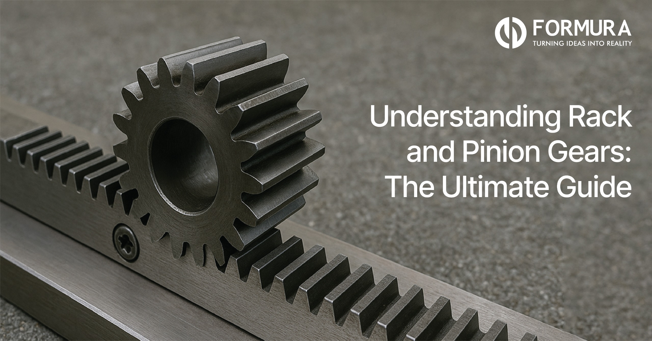
A rack and pinion is a pair of gears designed specifically to achieve one critical task: to convert rotary motion (spinning) into linear motion (straight-line movement), or vice versa. It is the workhorse of linear actuation, valued across nearly every industrial sector for its simplicity and robustness.
The question isn't whether your business uses this system, it’s how well you understand and maintain it. This guide will serve as your ultimate resource, explaining the components, detailing how does a rack and pinion work, exploring its core trade-offs, and highlighting its crucial role in industrial gearbox solutions and essential gearbox inspection maintenance services that Formura provides to keep our world moving.
Section 1: The Basic Components – Breaking It Down
The genius of the rack and pinion system lies in its minimal complexity. It consists of just two primary, complementary parts.
The Two Key Parts of the System
| The Pinion (Pinion Gear) | A small, round spur gear (a gear with straight teeth cut parallel to its axis). | This is the input component. It receives the rotary motion from a power source (e.g., a motor, a steering shaft, or an industrial gearbox). |
| The Rack (Gear Rack) | A flat, straight (or sometimes curved) bar with teeth cut along one edge. It is essentially a gear that has been "unrolled." | This is the output component. It produces the resulting linear (straight-line) movement as the pinion rotates. |
The interaction between the circular pinion gear and the flat gear rack is the key to motion conversion. The size of the pinion, measured by its pitch diameter, directly dictates the distance the gear rack moves per revolution. The specific geometry of the teeth on the rack and the pinion, known as the pitch, must match precisely for smooth, efficient operation.
Section 2: How Does a Rack and Pinion Work?
Think of a rack and pinion as a mechanical translator that turns "spinning" into "straight-line" movement. It uses a small, round gear called the pinion that meshes its teeth with a flat, notched rail known as the rack. When you rotate the pinion, like turning a steering wheel or a motor shaft, its teeth "walk" along the rack, pushing it forward or backwards. It’s a beautifully simple system that allows the circular motion of a machine to create the precise, linear path needed to move a car's wheels or slide a heavy industrial gate.
The principle behind the rack and pinion gear system is a direct application of basic mechanics. It converts continuous rotational input into precise, limited-travel linear output.
The Principle of Converting Motion
1. Input (Rotation): A power source, such as an electric motor or the shaft from a steering wheel or industrial gearbox, rotates the pinion gear.
2. Meshing of Teeth: The teeth of the spinning pinion engage precisely with the teeth on the stationary gear rack. The precision of this meshing is vital, as it determines the accuracy of the resulting linear movement.
3. Output (Linear Movement): As the pinion continues to turn, the teeth's meshing action "walks" along the rack, forcing the rack to move along a straight or curved path. The direction of the rack's movement depends entirely on the direction the pinion spins.
The result is a highly efficient and easily controlled mechanism. The fact that the teeth of the pinion gear move along the teeth of the gear rack ensures a positive, non-slip engagement, making gear rack and pinions indispensable in applications requiring reliable linear movement. The ratio between the pinion's circumference and the rack's linear movement remains constant, which is the basis for its high accuracy in positioning systems.
Section 3: Key Advantages and Disadvantages
Choosing a rack and pinion system over alternatives like belt drives or ball screws depends on a clear understanding of its inherent trade-offs, particularly for demanding industrial gearbox solutions.
Why Choose a Rack and Pinion System?
The rack and pinion system effortlessly converts rotary motion into precise linear movement. The pinion gear rotates smoothly while meshing its teeth with the flat gear rack.
This direct engagement ensures a powerful and non-slip transfer of mechanical energy. The modular design allows for nearly unlimited travel distances by joining multiple racks.
Engineers favor this setup for its high load capacity and exceptional durability. The mechanism provides a simple and reliable solution for steering and industrial automation.
Maintaining the system remains easy through regular lubrication and simple visual inspections. The constant ratio between the pinion and rack guarantees predictable and accurate positioning.
| Efficiency | High Efficiency: Simple design leads to minimal power loss compared to complex worm or helical screw systems. | Friction: Higher running friction than some alternatives (e.g., linear motors) requiring greater input torque. |
| Precision | Excellent Precision & Accuracy: Provides predictable and precise linear positioning, crucial for CNC and robotics. | Backlash: The slight necessary gap between the meshing teeth can cause a tiny amount of "play" or lost motion, which can harm precision (though expensive anti-backlash designs exist). |
| Travel & Capacity | Suitable for Long Travel Distances: The gear rack length can be easily extended by mounting multiple sections end-to-end. High Load Capacity: Can handle significant forces, especially with larger, hardened gears, making them robust. | Requires Proper Lubrication: Essential to reduce wear, heat, and noise generated by metal-on-metal tooth contact, necessitating routine maintenance. |
| Simplicity | Simple Design & Compact Setup: Generally easier to integrate and maintain than complex screw drives for long travel. | Noise: Can be quite noisy at high operating speeds, especially with straight-tooth designs. |
The key takeaway here is that a rack and pinion offers a robust solution for covering long distances with high precision and the ability to handle substantial loads—a combination that is often unmatched by other linear actuators, especially in heavy-duty industrial environments.
Also Read : Top Industrial Gearbox Maintenance & Inspection Tips for Peak Performance
Section 4: Common Types of Gear Racks
Depending on the specific job, whether it's moving a heavy industrial gate or guiding a high-speed CNC machine, different gear rack designs are used to balance power, noise, and precision.
The type of gear rack used directly impacts the system's performance metrics, such as smoothness, load capacity, and noise level. Choosing the appropriate rack is crucial for any industrial gearbox services project.
Choosing the Right Rack for the Job
- Straight Tooth Rack: This is the most common and economical type. Its teeth are cut straight and parallel to the axis of the pinion. While simple to manufacture and highly effective for most purposes, they are limited in speed and capacity compared to helical racks, and their noise profile is higher due to less overlap in tooth engagement.
- Helical Tooth Rack: In this design, the teeth are cut at an angle. This angled design allows more than one tooth to be engaged at any time, leading to:
- Smoother, quieter operation, even at higher speeds, making them ideal for high-speed CNC applications.
- Higher load capacity and better resistance to shock loads than straight-tooth racks.
- Note: Helical racks generate a side force (thrust load), which the mounting system must be designed to accommodate, often requiring thrust bearings in the industrial gearbox output shaft.
- Curved Rack: Less common, these racks are manufactured with a curved profile instead of a straight one. They are used for niche applications that require linear motion along a specific radius or curved path, such as telescope mounts or specific automation jig movements.
Section 5: Real-World Applications of Rack and Pinion
The versatility of the rack and pinion system makes it a foundational component across countless industries. When these systems are powered by an industrial gearbox, they become part of a larger, robust industrial gearbox solutions package.
Where You'll Find Rack and Pinion Systems in Action
Automotive Steering
The most familiar application. When the driver turns the steering wheel, the steering column rotates the pinion gear. The pinion then drives the gear rack linearly to the left or right, turning the wheels.
CNC Machinery & Gantry Systems
In CNC routers, plasma cutters, 3D printers, and large gantry robots, rack and pinion systems provide the necessary speed and accuracy for moving the cutting head or tool along the long X, Y, and Z axes. Their ability to cover extended travel distances with high precision is key here.
Industrial Automation
These systems are widely used in material handling for precision movement:
- Sliding Doors and Gates: Used to open and close heavy industrial doors smoothly.
- Conveyor Systems: Guiding product placement and movement along assembly lines.
Lifts and Hoists
In some elevator designs and heavy-duty jacking systems, a vertical gear rack is fixed, and a powered pinion gear (often connected to an industrial gearbox) drives the entire platform or cage up and down the rack, providing a reliable safety mechanism against slippage.
Criticality of Formura’s Gearbox Maintenance
Because the rack and pinion is often the output stage of a larger mechanical drive, its reliability is tied to its power source. Reliable industrial gearbox services—including gearbox inspection maintenance services—are non-negotiable for longevity. Formura acts as your dedicated gearbox services provider, focusing on:
- Pinion-Rack Alignment: Ensuring perfect tooth meshing to minimize wear and backlash.
- Lubrication: Applying the correct viscosity and type of lubricant to the teeth to reduce friction, heat, and noise.
- Vibration and Wear Analysis: Using diagnostic tools to monitor the industrial gearbox and rack system for early signs of failure, preventing costly unplanned downtime.
Conclusion
The rack and pinion is a testament to simple mechanical brilliance. It is a simple, robust, and highly effective mechanism that reliably converts rotary motion into linear motion, underpinning everything from the responsive steering of your car to the precise movements of advanced industrial automation.
For any business utilizing linear motion, understanding the operation and demanding high-quality gearbox inspection maintenance services from a trusted partner like Formura is not just good practice—it is critical to ensuring efficiency, precision, and longevity in your operations.